Correct drive alignment is important to the safe and proper operation of General Kinematics shaft driven equipment.
Improper Drive Alignment can cause:
Spring Breakage
Poor Conveyance
Bearing Failure
High Motor Amps
And more
Any time major repairs or modifications are made to the machine the drive alignment should be checked.
Safety First:
Lockout: Lockout all related machines being worked on in accordance with your facilities Lockout-Tagout procedures.
Machines must be at Zero Mechanical State. (This normally means that the eccentric on the shaft will be hanging down.)
Review the Safety section on page 1 of all of General Kinematics Service Manuals.
Preparation:

- Check that the machine is empty and that there is nothing interfering with the movement of the trough or the balancer. Such as the material spillage that is accumulated under the unit, or contact with another unit.
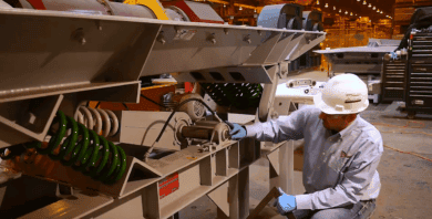
- Remove the drive guards or covers.
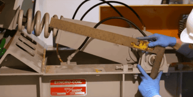
- Verify that eccentric drill marks are in the bottom position. ***Safety Note: Never place your hands or body parts between the belts and sprockets. There is always a potential for stored energy in the system that could cause the shaft to rotate without warning.***
Checking and Adjusting Drive Alignment:
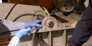
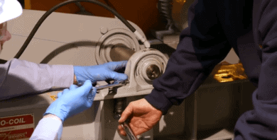
1.) Define our reference lines the first is aligned through the drill marks at the end of the shaft. The second line starts at the offset drill mark at the end of the shaft and extends through the centerline of the driveline.
2.) The drive is aligned when these two lines are at 90 degrees. Adjust using a square.
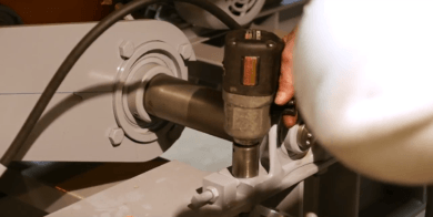
3.) If the drive alignment needs adjustment, start by loosening the pillow block bearing mounting bolts and then back off the jam nuts on the bearing stop bolts towards the end of the bolt.
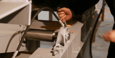
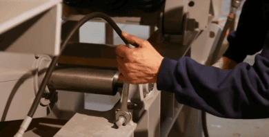
4.) Rotate the eccentric shaft to position the drill marks 90 degrees to the center line in the drive arm.
Eccentric shaft rotation is accomplished by turning the baring stop bolts in or out. Thus moving the pillow block bearings forward or backward until the 90-degree angle requirement is achieved.
5.) Repeat the previous step for the non-driven side.
6.) Recheck the driven side alignment after completing the non-driven side alignment.
7.) Tighten the pillow block bearing mounting bolts for the fastener torque chart in the service manual.
8.) Ensure that the bearing stop bolts are tight against the pillow block bearings.
9.)Tighten the bearing stop bolt jam nut securely and ensure that the bearing stop bolts are locked in position.

10.) Replace the guards
11.)Retighten all fasteners after a short run period
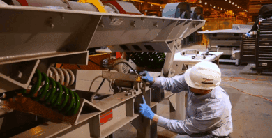
An alternate method of checking the drive alignment can be accomplished utilizing a digital level
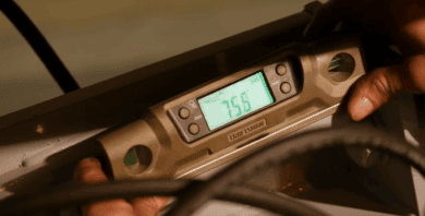
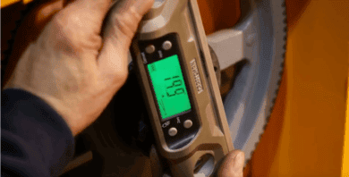
- Measure the angle through the drill marks on the end of the shaft
- Place the level on the theoretical line that runs from the eccentric drill mark through the centerline of the drive arm
- The sum of these two angles should be 90 degrees
If you’re unsure if the repairs or modifications you’re planning to do will affect the drive alignment, please contact us. We want to make sure that you take all appropriate steps to ensure your safety, success, and the long-term integrity of the machine.